Initially Chloe and I were able to successfully perform the tasks asked of us in the SciBorg assignment, but during the last couple we were having trouble with our SciBorg getting caught on the tape line, which made it difficult for us to test our code. Although it was frustrating at points, overall I enjoyed problem solving with the SciBorg and Arduino.
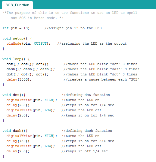
1.) Making Functions
3.) Working with Our SciBorg
Both Motors:
In order to have both both motors running simultaneously, we edited the “single motor” sketch by copying the lines of code used to control motor 1, and changing them to do the same to motor 2.


Minimum Speed:
We found that the minimum speed of our SciBorg “73” by slowly decreasing the speed of both motors until the SciBorg no longer moved when the code was run.


Hard Turn:
To make our SciBorg make a hard turn, we made one motor turn forward quickly and the other turn backward quickly.


Gentler Turn:
To have our SciBorg make a more gentle turn, we kept both motors turning in the same direction, but made one turn faster than the other. This caused the SciBorg to turn towards the direction of the slower turning motor.

Traveling 10 Feet:
During an initial test, it took our SciBorg around 18 seconds to travel 10 feet. We then programmed it to stop moving forward after 18 seconds and it stopped moving right around the end of the 10 foot course.


4.) Feedback With Sensors
Motor Encoder:
Even though the code is telling the motor to move forward for one second and backwards for one second, the motor position does not go back to it’s initial position after two seconds. One reason this happens is because the motors have momentum, so they cannot stop and switch directions instantaneously when the code tells them to. It takes time for the motor to slow down and switch directions, which shortens the time it travels in the other direction.
Light Sensor:
Using the light sensor on our SciBorg, we saw a range of 0-97 and these values seemed fairly accurate. We did not see a noticeable difference in the accuracy when the LED was turned on, but we did notice a change in accuracy as the distance changed. If values seemed most accurate when the light sensor was around 2cm above the surface it was sensing.


5.) Drive Straight
Setting both motors to the same speed did not result in our SciBorg moving in a straight line. In order to have it do so, we use -bang-bang controls to change the speed of one motor while keeping the other constant. First we fixed motor 1’s speed at 230. Then, if motor 2 was moving more slowly than motor 1, we set motor 2’s speed to 250. If it was moving more quickly than motor 1, we set its speed to 210. If neither was true, we set the motor speeds equal to each other. This method allowed our SciBorg to move in a net direction of a straight line, but it moved back and forth repeatedly while doing so.


6.) Driver Straighter
In order to make our SciBorg move in a straighter line, we used proportional control. Proportional control makes use of an error (the target – the present state) and the proportional gain coefficient (kp) in order for changes to be made proportional to how far off the current value is from where you want it to be. We set our error equal to motor 1’s speed – motor 2’s speed and our kp equal to 1. Again we kept motor 1’s speed constant, but altered motor 2’s speed by +/- kp*error. When motor 2 is moving more slowly than motor 1, the error (motor 1’s speed – motor 2’s speed) is greater than zero, and we want to add the error to motor 2’s speed in order to have it equal motor 1’s. When motor 2 is moving more quickly than motor 1, the error is less than zero, and we want to subtract the error from motor 2’s speed in order to have it equal motor 1’s.


7.) Bang-bang Line Following
To have our SciBorg follow the line, we programmed it to follow the edge of the tape. We found that the light sensor read half white/half brown to be around 20. We started our Sciborg on the left of the line. When it was reading above 20, it means that it is over the white line and needs to turn left, so we have motor 1 set to 100 and motor 2 set to 200. When it was reading below 20, it means that it is over the brown and needs to turn left, so we have motor 1 set to 200 and motor 2 set to 100. When attempting to have our SciBorg follow the line, both the metal ball and the tires were getting stuck on the tape that forms the line. We tried lubricating the ball, altering the speed, and switching to a different type of tire, but we were not able to effectively test our code.

8.) Proportional Line Following
For the proportional line following, we combined our “Drive Straighter” code with our “Bang-Bang Line Following” code. We set the error equal to 30 – the scaled reading of the light sensor. If the error was greater than zero, the light sensor was over the brown surface and we increased motor 2’s speed to turn the SciBorg towards the line. If the error was less than zero, the light sensor was over the white line and we decreased motor 2’s speed to turn the SciBorg in the opposite direction towards the line. When testing our code, we had the same issues with the SciBorg as with Bang-Bang Line Following.


It’s interesting that you narrowed down your issues with bang-bang and proportional line following to the unevenness of the tape. I think Keer and I were facing a similar problem which would result in inconsistent trial runs.
It’s nice to see how you adapted when presented with issues. I also love how you have annotated every line of your code— it really helps in understanding the function of each line.