This past week, I have mostly been focused on hardware, and transitioning (ha, get it) from my mock-up to a more accurate prototype.
First, I laser cut all of my pieces! To ensure a clean cut, we cut test squares out of the plywood to optimize the laser cutter settings, before cutting all the pieces of my box.


All of them came out as expected, except the center divide, which was 0.5 cm too long on one side. Larry and tablesaw to the rescue!
For the gear train, I drill pressed a lego gear and used super glue to fix it to the servo motor.
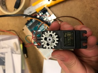

Then, I marked out the places on the side panel where there needed to be holes for axles, and drill pressed them. That way, I could stick the gears through the wood, and then mount them to legos in the back. The extra gear on the inside is for the servo motor driving the train.


I had laser cut holes for the buttons, and they fit nicely! Each button came with a nut I could use to fix the button in place.

Certain panels, such as the top with the frame and the side panel with the gears could be glued together on their own, but with the rest of the assembly, I found that I needed to solder as I went along. There was a lot to keep track of! I’m glad it went as smoothly as it did.
First, I put the buttons in series with the battery pack, threading the battery pack through the center divide, and leaving enough wire so the battery pack can be pulled out when the batteries need to be changed. Unfortunately, it cannot completely detach, simply because there weren’t enough “male” and “female” wire ends on hand that I could use to make a junction after the buttons in series. Still, there is ample room to remove the pack.
One thing I noticed as a result of testing the buttons, battery pack, and arduino in series with the breadboard was a lag of a few seconds. The buttons were pressed, then the arduino would turn on, read the photocell, and only then would it turn on the lights. I will be sure to mention this to Professor Gleason.

Separately, I soldered wire to each LED, making sure to keep red on the positive end and blue on the negative end, and using a truly excessive amount of heat shrink tubing to make sure the two ends wouldn’t cross in the LED sockets.
I also prepared the protoboard separately, soldering in the pre-measured jumper wires and resistors for the LEDs, as well as the flexible jumper cables that would plug into the Arduino and Servo. The Arduino will be solely connected through pins, so it is completely recoverable.
To integrate the LEDs and Arduino, I had to thread the LED wires through the center divide, but because the 0.5 cm had been trimmed off one end, there were no longer enclosed holes to keep the wires in check. I temporarily fixed this with some electrical tape, but eventually the side panel covering it would solve that problem. I then soldered the negative ends to the protoboard, leaving the positive ends free to plug into the arduino pins.
The Servo motor is taped out of the way to the top of the center divide, and it is also completely recoverable (except that a lego gear is superglued onto it). The motor attaches to pins that are soldered onto the protoboard.
All of the wires were cut on the long side, to avoid the sticky situation of wires unable to reach the protoboard or Arduino. They were then somewhat organized and fixed with electrical tape.
Now that all of the pieces were in place and the connections were working, I could join all of the pieces together using wood glue. Since I couldn’t figure out how to clamp perpendicular to a surface, I ended up clamping with painters’ tape.

At one point, I wanted everything to stay squished in place, so I weighed it down with a power drill. To avoid crushing the LEDs on the bottom (since most of my assembly was done with the box upside down), I placed a strip of wood underneath as a sort of shim.

Then I left for dinner!
And when I came back, poof! 4/6 faces done! And when I taped the other 2 faces on, everything stayed put! It all fit in the box!

Leaving one of the side faces and the bottom panel open means that I still have enough room to manipulate the insides. I also left the Arduino port open, though I haven’t had a need to modify my code.

Plus, just enough is assemble that it can still pass for complete in pictures 🙂 My poster is ready to go, and my project will debut under its new name the Blink Block.

Final To-do List
-For some reason, the motor doesn’t want to work. It worked when I first made it on the breadboard, and kept working after I first soldered it in, but when I squished it with the rest of the box, something made it not work again.
-I would like to round the edges slightly, whether with a router or a belt sander. Once that is done…
-…The gear panel and bottom photocell panel needs to be fitted with an acrylic coat. I found that super glue works well on acrylic-wood joints

I love the creative adaptations you have made to get all the pieces of your device to fit into the box.
You made a lot of progress! I think it is cool how you created your own box using solid works to exactly fit your vision.
Nice and detailed! Dinner is important! Love that picture that is labeled, very fancy.