From start to finish, Julia’s and my vision of our windlass stayed pretty consistent from sketch to prototype to model. We decided upon a base with a rectangular structure, connected at the top and bottom.
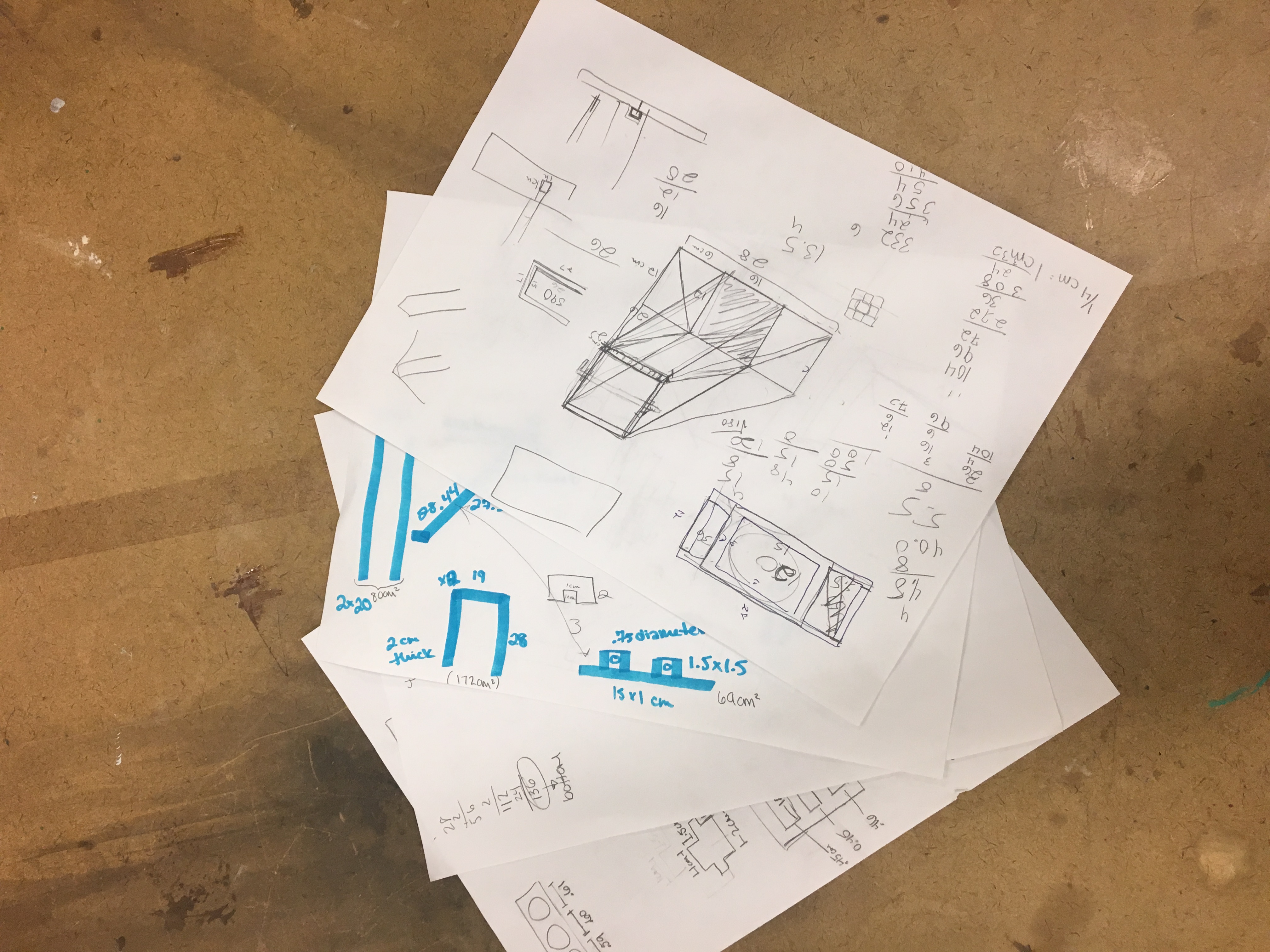
With this idea in mind, we created a foam core model. However, it was evident that there was not a sufficient amount of support between the sides with just horizontal supports. From the brief beginning presentation, it was clear that a triangle would increase the stability of our project. Thus, we decided that there should be triangular supports on both sides of the windlass to provide it with a sturdier structure, a beam running diagonally from top to bottom of the rectangular structure.

After creating a solid model that we were happy with and well under the material constraint, we moved on to laser cutting our 6 basic parts. We used a lot of heat staking and press fits to connect pieces together so we created testing pieces to see what size to make all of the slots in our parts.
Recent Windlass Top and Support-xo25i3
The only other issue we faced from there was how to use the delrin rod to crank the water bottle up. It’s a relatively flimsy piece so one length of the rod wouldn’t do the job. We decided to cut the larger rod in half and use the two resulting smaller rods to equally distribute the weight of the water bottle, both being turned at the same time by a conjoining handle.

Once we got all of the pieces to fit together, we realized that the supporting side pieces weren’t enough to keep the structure stable. Thus we added another bar running from one side of the windlass to the other.
Final Winldass Sides and Supports-tsbh0n
After heat staking the parts together and press fitting the bottom parts to the rectangular sides, everything was very sturdy and secure. Next, we attacked how the create the handle for the two rods. We used a combination of press fit and tight fit bushings to secure the rods and handle in place. Which resulted in a very easy and manageable way to wind up the windlass.

Our final product turned out very sturdy and supportive in its structure, serving its purpose in the demo.

Engineering wise, our structure was very sturdy and did not bend, due to the structural support created by the triangle formed by the beams on the side. It was successfully able to lift the bottle to the start of the green label because of the concept that triangles are the only shape where the sides and angles of the shape cannot change without an associated change in length or angle, rendering then as very stiff structure. We figured pretty close to the beginning that this triangular support was going to be very important our design so we were able to finish with the allotted amount of time. We could change the length and the hight of the delrin that we used but we could change the width (we were constrained to 1/8th”) or the fact that they would have to intersect at 90 degree angles.
Overall, I really liked our design. The handle was a pretty clever addition that I really liked about it. However, this meant we couldn’t wind up the bottle from the floor which was one of the requirements of the project. In addition, it required a lot of material which wouldn’t be the most effective and efficient way of building a well windlass in reality. If we had more time, I would have liked to explore a similar design but figure out just how high and long and wide each of the pieces needed to be at minimum for the windlass to remain sturdy and supported, saving some extra material.
Areas:
Bases- 112 cm^2
Sides- 268 cm^2
Supports- 97 cm^2
Bushings- 6.3 cm^2
Handle- 16.5 cm^2
Total- 499.8 c^2

The way you used two strings and two axles to distribute the weight was really clever! Nice job 😀